
Recently, I came across shocking data: 73% of hardware product recalls stem from issues that never appeared during traditional lab testing. That means your clean, controlled development environment is lying to you about how your hardware will behave in the wild.
This is the reason most companies work with professional development services providers to test products with real-time scenarios to find out flaws before the product hits the market.
Professional hardware development services increasingly rely on Hardware-in-the-Loop (HIL) testing to bridge this dangerous gap between lab results and real-world chaos.
In this article, I have listed the five failure points why your product fails and how HIL can help.
Let’s start!
What is Hardware-in-the-Loop (HIL) Testing?
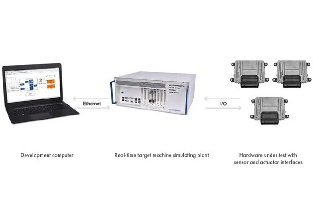
Hardware-in-the-Loop (HIL) testing is a testing technique used to develop and validate embedded systems by integrating real hardware with a simulated environment.
Instead of testing a system in its fully assembled state, HIL allows engineers to connect a controller to a virtual model that mimics real-world conditions, enabling them to identify product flaws and issues that can be fixed immediately.
Why Your MVP Fails – 5 Failure Points
1. Real-World Signal Interference You Never Saw Coming
Your development lab is an electromagnetic monastery. Stable power, minimal RF noise, carefully protected equipment. But the real world is electromagnetic warfare.
What Goes Wrong?
Sensors fail mysteriously near WiFi routers. Motors stutter when industrial equipment powers up nearby. Communications drop randomly in office buildings packed with wireless devices.
Common interference sources that blindside hardware:
- 2.4GHz WiFi overlapping with Bluetooth and sensors
- Fluorescent lighting creates power line noise
- Cell tower handoffs disrupting sensitive receivers
- Electric motor switching transients
Why HIL Catches This?
HIL testing lets you inject real-world interference patterns during development. You control the chaos instead of discovering it after production.
Interference simulation capabilities:
- RF signal injection across frequency bands
- Power line noise generation
- Electromagnetic field simulation
- Multi-protocol interference modeling
Implementation
Environmental chamber integration combines temperature stress with RF injection. Your hardware faces multiple stressors simultaneously, just like deployment.
Frequency sweep testing reveals vulnerable frequencies. Automated sweeps from DC to several GHz expose hidden susceptibilities.
Test setup example:
- Signal Generator → RF Combiner → Device Under Test
- ↓
- Spectrum Analyzer monitoring emissions
- ↓
- Automated pass/fail criteria
2. Temperature and Environmental Edge Cases
Your components have split personalities. They’re well-behaved at room temperature but become unpredictable when stressed by real environmental conditions.
What Goes Wrong?
Batteries drain 50% faster in freezing conditions. Sensors drift unpredictably in summer heat. Solder joints crack under thermal cycling. Connections corrode in humidity.
Temperature-related failure modes:
- Crystal oscillator frequency drift
- Battery capacity degradation
- Sensor calibration shifts
- Thermal expansion stress
Why HIL Catches This?
HIL systems integrate climate chambers with functional testing. Your hardware runs real workloads while temperature and humidity cycle through extremes.
Traditional testing checks functionality at fixed temperatures. HIL testing stresses functionality during temperature transitions, when most failures occur.
Implementation
Automated temperature cycling runs your full test suite at every temperature point. No manual intervention, no forgotten test conditions.
Long-duration stress testing protocol:
- Baseline performance measurement at 25°C
- Gradual temperature ramp while monitoring key parameters
- Soak testing at temperature extremes
- Thermal shock transitions
- Performance verification after cycling
Climate data logging captures performance degradation patterns. You see exactly when and how performance degrades with temperature.
3. Timing Issues That Only Appear Under Load
Your carefully timed sequences work perfectly in isolation. Add system load, multiple processes, or peak usage scenarios? Timing goes out the window.
What Goes Wrong?
Sensor readings get skipped when CPU load spikes. Response times stretch beyond acceptable limits. Buffer overflows crash systems during peak usage periods.
Typical timing failure scenarios:
- Interrupt priority conflicts
- Resource contention issues
- Memory allocation delays
- Communication protocol timeouts
Why HIL Catches This?
HIL testing generates realistic system loads while measuring timing precision. You see exactly when and where timing constraints break.
Simultaneous stress testing pushes multiple subsystems at the same time. Real deployments rarely stress single components in isolation.
Implementation
Concurrent stress testing runs maximum loads on CPU, memory, I/O, and communications simultaneously.
Timing analysis setup:
- High-resolution timestamp logging
- Interrupt latency measurement
- Real-time constraint verification
- Statistical timing analysis
Automated load patterns replicate real usage scenarios. Peak usage, sustained operation, and burst loading all get tested systematically.
4. Integration Failures Between Hardware Components
Individual components pass their tests with perfect scores. But put them together and you’ll get mysterious failures that emerge from component interactions nobody predicted.
What Goes Wrong?
Power supply switching noise corrupts analog measurements. Digital circuits interfere with sensitive radio receivers. Ground loops create instability that appears randomly.
Integration failure patterns:
- Power supply noise coupling
- Ground loop formation
- Electromagnetic interference between subsystems
- Signal integrity degradation
Why HIL Catches This?
HIL testing exercises complete system integration with real component interactions. You discover interference patterns that only appear with full system operation.
System-level scenarios stress component combinations under realistic operating conditions. Individual component testing misses these interaction effects entirely.
Implementation
Power quality monitoring tracks supply noise, voltage ripple, and current transients during full system operation.
Signal integrity verification checklist:
- Crosstalk measurement between signal paths
- Power supply noise analysis
- Ground impedance verification
- EMI/EMC pre-compliance testing
Integration test matrices cover all critical component combinations. You don’t rely on luck to find problematic interactions.
5. Long-Term Reliability Issues
Your hardware looks robust after weeks of testing. Performance degrades mysteriously as components age in ways your short-term tests never revealed.
What Goes Wrong?
Component parameters drift over months of operation. Electrolytic capacitors lose capacity. Calibration drifts. Mechanical wear creates new failure modes.
Long-term degradation mechanisms:
- Electromigration in conductors
- Dielectric breakdown in capacitors
- Sensor drift and calibration loss
- Mechanical wear in moving parts
Why HIL Catches This?
HIL systems run accelerated aging protocols and continuously monitor performance parameters. You compress months of aging into weeks of testing.
Continuous data logging captures gradual performance degradation. You see failure curves develop instead of discovering failures after deployment.
Implementation
Temperature cycling accelerates most chemical aging processes. Higher temperatures increase reaction rates predictably.
Accelerated aging test matrix:
- Temperature stress (85°C vs. 25°C = 8x acceleration)
- Voltage stress (increases electromigration rates)
- Humidity cycling (accelerates corrosion)
- Mechanical cycling (tests wear patterns)
Predictive failure analysis identifies components approaching end-of-life before they fail. You predict field failures instead of reacting to them.
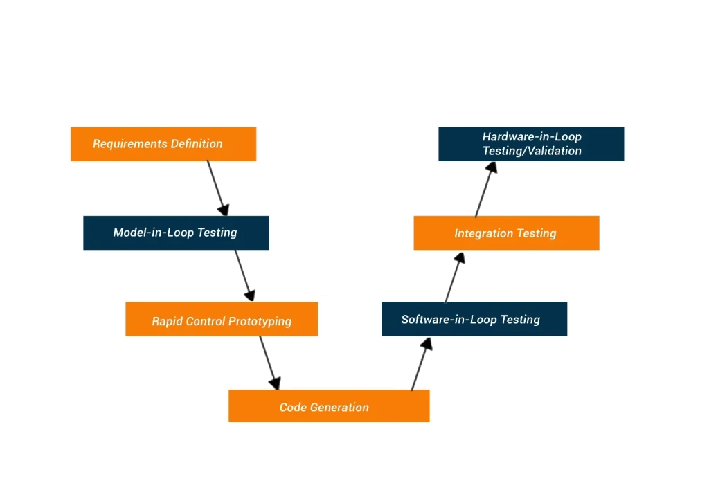
Building Your HIL Testing Strategy (Priority Order by Hardware Complexity)
Here are some essential steps for building your HIL testing strategy:
- Simple embedded devices (single board, basic I/O): Start with environmental testing and basic interference simulation.
- Communication-heavy products (IoT, wireless): Prioritize RF interference and real-world signal conditions.
- Multi-component systems (automotive, industrial): Focus on integration testing and component interaction analysis.
- Safety-critical applications (medical, aerospace): Implement full spectrum HIL with timing, environmental, and reliability testing.
- Consumer products with reliability concerns: Emphasize accelerated aging and long-term degradation testing.
DIY vs. Professional HIL Testing (When to Build vs. Buy)
Confused about when to do professional HIL testing or DIY? You should:
- Build in-house when: Your team has RF/test engineering expertise, you need ongoing product iterations, testing requirements are specialized for your domain.
- Outsource when: Initial product development phase, limited testing expertise in-house, cost of HIL setup exceeds 20% of development budget.
- Hybrid approach: Partner with professional services for initial HIL setup and training, then maintain internal capabilities for ongoing testing.
- Red flags for DIY: No dedicated test engineer, underestimating setup complexity, trying to build HIL capabilities while developing your first hardware product.
Conclusion
If your MVP uses HIL testing, it can identify its current state and determine its desired direction. Not performing this step can lead to a product that gives unpredictable results in the market, causes expensive mistakes, and faces unnecessary delays. HIL testing links simulation to reality, which helps your system become strong, dependable, and suitable for use. Failing to use HIL testing will most likely keep you from seeing positive results with your MVP.